ENGINEERING SERVICES
Engineering Solutions for Every Project
Crowley’s engineering services team delivers a full range of marine and engineering solutions. These include conceptual and detail design, shipyard management, and onsite consulting for marine projects worldwide.
Our marine engineering and vessel design services are cost-effective and extraordinary. No matter the size and scope of your marine project, our engineering services professionals will assist you in achieving your objectives in the safest, most efficient manner.


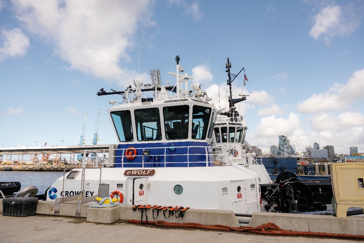
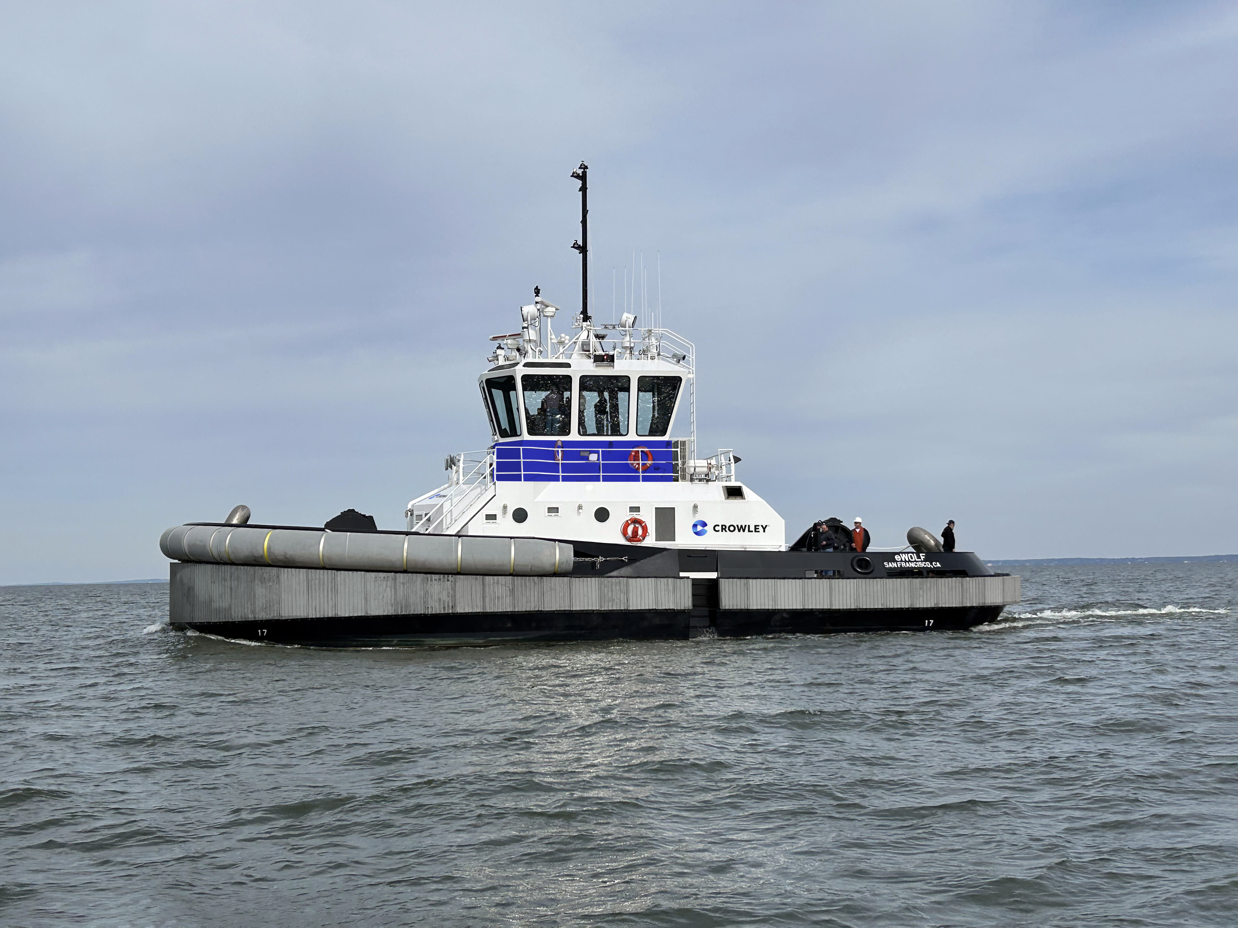
Crowley Accepts Delivery of eWolf, the First Fully Electric Tugboat in the U.S.
Crowley has accepted delivery of eWolf, the first all-electric, ship assist harbor tugboat in the U.S., a milestone advancing the company’s commitment to sustainability and decarbonization.
The tugboat, which was designed by Crowley’s engineering services team, will operate with zero emissions while providing the complete performance capabilities of a traditional tug.
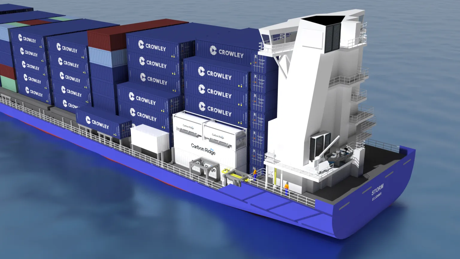
Carbon Ridge, Crowley to Launch Advanced, Onboard Carbon Capture Project
Crowley and Carbon Ridge Inc, a leading developer of modular onboard carbon capture and storage solutions (OCCS), with support from the U.S. Maritime Administration (MARAD) Maritime Environmental and Technical Assistance (META) program, have initiated an advanced, pilot project to reduce emissions impacts using Crowley’s Storm international container ship.
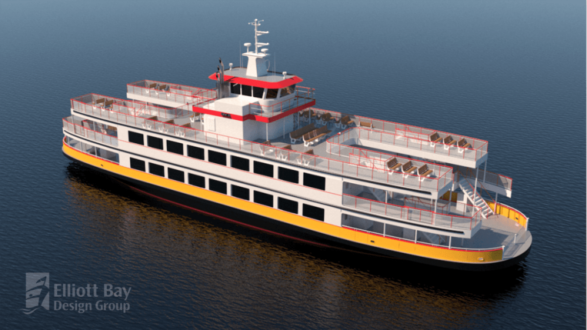
Crowley Secures Subcontract for Hybrid-Electric Ferry
Crowley has been selected by Senesco Marine to provide design verification and production packaging for a hybrid-electric passenger vehicle ferry for Casco Bay Lines of Portland, Maine. As part of an elite project team, Crowley brings expansive capabilities in sustainable, emissions-reducing design and construction services.
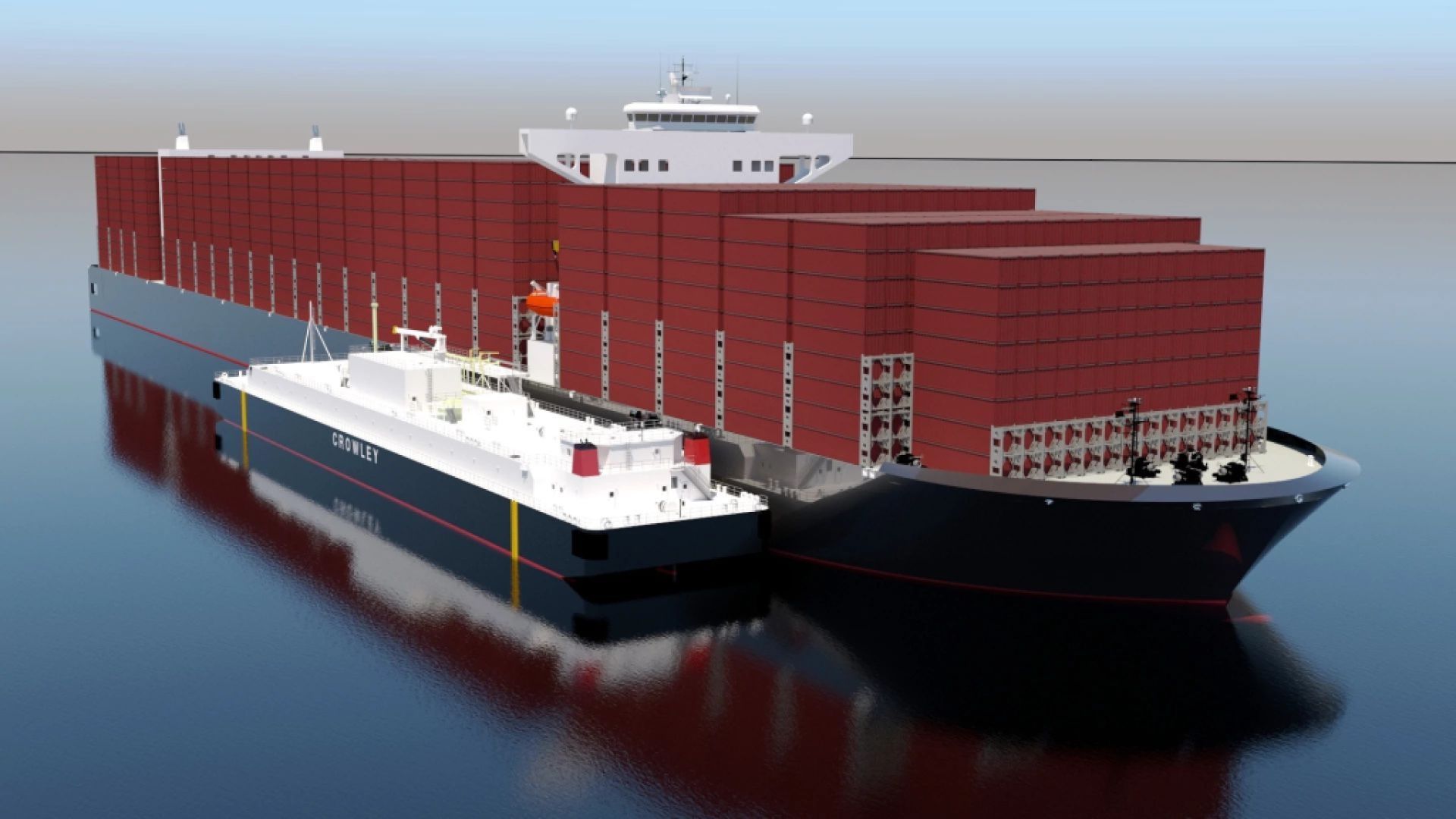
Crowley and Shell to Build and Charter Largest LNG Bunker Barge in US
Crowley Maritime Corporation has signed a long-term time charter with Shell NA LNG, LLC, (“Shell”) providing for the building and operation of a new, U.S.-built, LNG bunker barge. Upon construction, the barge will be the largest Jones Act-compliant vessel of its kind, helping to expand current network capacity and meet demands for cleaner energy.
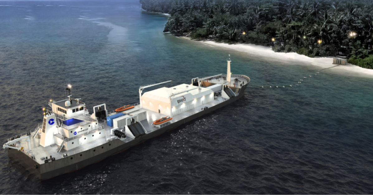
Crowley, BWXT Debut Nuclear Power Generation Vessel Concept
Global shipping and energy supply chain leader Crowley has teamed with nuclear power leader BWX Technologies, Inc. (NYSE: BWXT) through a memorandum of understanding for a ship concept that has the potential to generate alternative, zero-carbon emission energy for defense and disaster needs by including a microreactor on board.
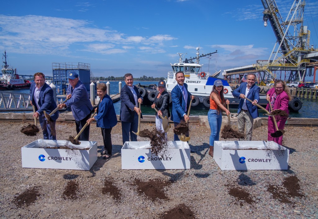
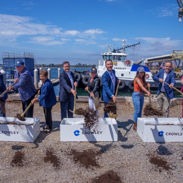
Crowley, Port of San Diego Celebrate Groundbreaking for All-Electric Tugboat Charging Station
Crowley and the Port of San Diego broke ground for the shoreside charging station designed to provide clean energy for the company’s forth-coming zero-emissions tugboat, eWolf.
The charging station is a microgrid charging facility that will allow vessels to recharge quickly while reducing peak loads on the community energy grid. It is equipped with two containerized energy storage systems provided by Corvus Energy, a leading supplier of reliable energy solutions in the maritime sector.
Engineering Services Achieves ISO 9001:2015 Certification
Crowley Engineering Services (CES) has achieved ISO 9001:2015 certification from the International Organization for Standardization (ISO) recognizing the business group’s capabilities.
Widely considered as the worldwide standard for quality management systems and practices, the ISO 9001:2015 certification, audited by Platinum Registration, reinforces Crowley’s process and management system as efficient, repeatable and robust.
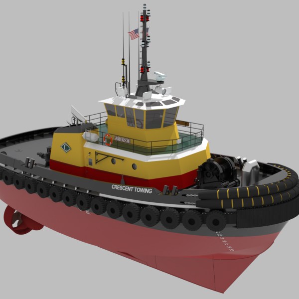
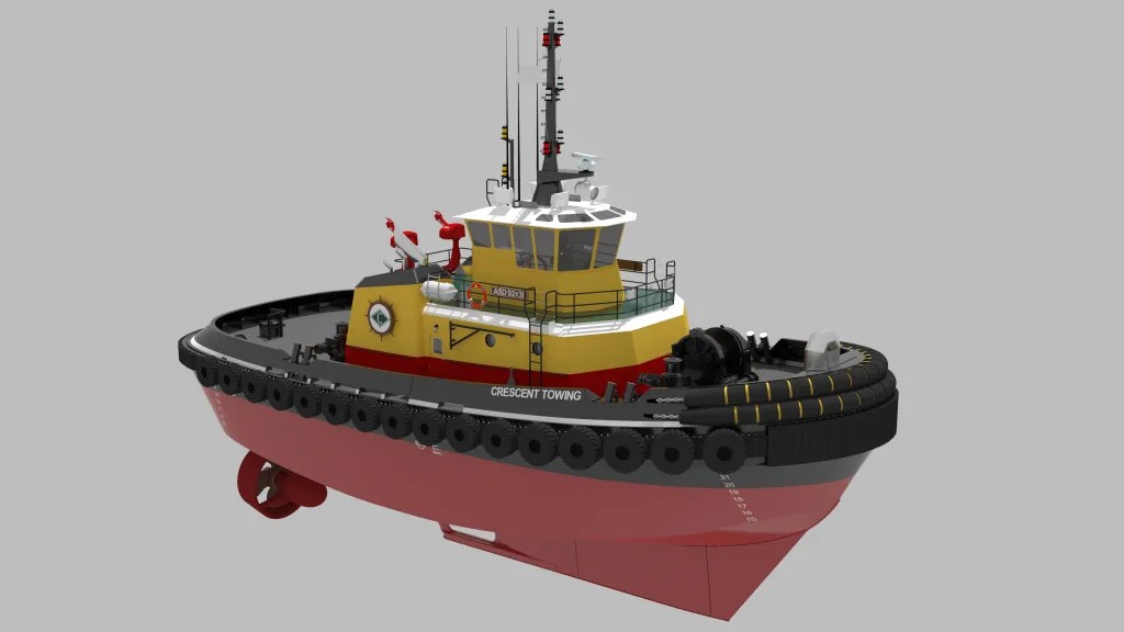
Crowley Engineering Services Wins Design, Production Contracts for Crescent Tug
Crowley has won the design and production contracts for a 92-foot Tier IV ship assist tugboat for owner-operator Crescent Towing.
The new tug design offers enhancements from the existing Crowley Engineering Services-designed tugs for Crescent, including additional horsepower that increases the vessel’s capability to meet demanding operational requirements.
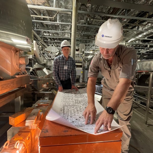
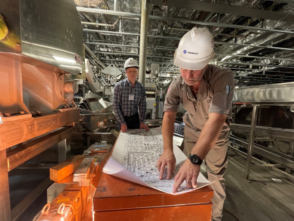
The most experienced engineers, designers, and project managers in the business
Our naval architects and marine engineers have award-winning experience designing high-productivity vessels and engineering solutions that meet or exceed regulatory and environmental standards. That translates into high-performing and successful project execution across all sectors of the marine industry.
Work performed includes, but is not limited to: Engineering for vessel conversion and modification, feasibility and proof-of-concept studies, FEED studies, heavy-lift transport engineering, mechanical, piping, and electrical system engineering, naval architecture, and stability and structural analysis.
Leading the industry into the next generation of offshore wind
Developers have plans to bring over 11,000 MW of offshore wind online by 2026. This includes 13 offshore wind projects in U.S. waters. As a turnkey wind services provider, we are technically and functionally prepped to partner from shore to sea. Our team of experts combines decades of project management and engineering; port operations and terminaling services; maritime prowess; and logistics expertise to marshal or develop the appropriate equipment, personnel/crew and materials from the supply chains, and deliver them to the right place in time for deployment.
Leading the industry into the next generation of vessel design
Pioneers of innovative, high-powered ship assist tugboats, Crowley will lead the next generation of industry sustainability by building and operating eWolf, the first all-electric powered harbor tugboat in the US. It can complete a job without expending a drop of fuel, and with its 70 tons of bollard pull, it’s the most powerful all-electric tug in the world. Become a part of what we’re doing at Crowley. To bring us onboard for your next Engineering or Naval Architecture project, get in touch with us today.
Meet the Crowley Engineering Services Management Team

Cole Van Gundy
Vice President
Engineering Services

Ray Martus
Director
Contracts
Patrick Sperry
Director
Projects

Curt Leffers
Director
Research and Development

Eric Rose
Sr. Director | Ports and Infrastructure
Business Operations

Bryan Nichols
Director
Commercial Operations

Charlie Jors
Chief Naval Architect
Naval Architecture